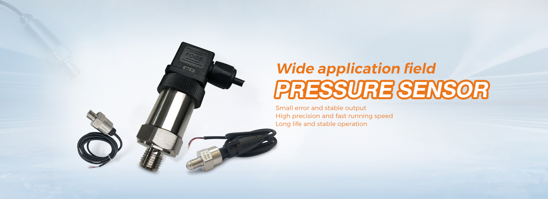
Hodie capimus orificium laminam differentiale pressura transfusor ut exemplum illustrare institutionem positus cum metimur Gas, liquida et vapor.
(I) metimur liquidum medium
When the transmitter measures the pressure or differential pressure of the liquid, it is mainly to prevent the liquid entering the conduit from mixing with gas and accumulating in the pressure guiding pipe, so that the static pressure head changes.For this purpose, the transmitter should be installed at or below the level of the pressure measuring point, as shown in Figure 5.4(a).If the transmitter has to be installed above the pressure measuring point, move the pressure guiding tube down a distance from the pressure measuring point and then upward to form a U-shaped tube, so that the gas in the liquid can be released as soon as possible.At the top of the conduit, a gas collector or a vent valve should be installed, as shown in Figure 5.4(b).Whether it is above or below, if there is sediment in the liquid, in order not to block the conduit, a settler is required.If the liquid to be tested is aut viscosa, an isolator sit installed, et installation positio ostenditur in Figura 5.4 (c).
(A) Transmitter Undered (b) Transitor super throttling (c) transmitter installation usura isolators
1- throttling fabrica; II -a Isolator; 3 A differentialis pressura transmitter
5,4 mensuræ Gas installation
(II) mensuræ Gas medium
Cum transfusor mensurat differentialis pressura vel pressura de Gas, quod maxime est ne liquidum et pulveris a intrantes pressura gens pipe, ita ut stabilis pressura capite mutationes et mensurae errorem crescit. Propter quod transfusor sit installed super pressura mensuræ point.If non habet installed inferius, necesse est ut install a coluber et stabilibus in infimo puncto et pulvere. Si mensuræ mordive vapores, an Isolator sit etiam installed.figure 5.5 ostendit mensurae Gas installation location.
(a)Transmitter supra throttling (b) transfusor sub throttling
I-throttling fabrica; II, A Isolator:
Figura 5.5 installation situ mensuræ Gas
(III) mensuræ vapor medium
Cum transfusor mensuras vapor vapor intrat transfusor mensuram camera in statu condensate.If non neglegenter patitur vapor intrare transfusor, quod non damnum, ut sit installed.for in duas balance, et ut liquido in duas blasphemarent, et ut in duas balance.because Vapor est metiri in liquido statu transfusor sit installed infra; Si habet installed supra, a Gas collector vel spiraculo valvae sit installed.The installation positus in mensurae vapor medium est ostensum est in figuras 5,6 (a) et 5.6 (b).
(a)Transmitter sub throttling (b) transfusor supra throttling
I-throttling fabrica; II-a lege; III-A transmitter
Figure 5.6 mensuræ in installation situ de fumo medium
(IV) Installation of mensuræ Liquid Level
(a)Transmitter sub throttling (b) transfusor supra throttling
1- throttling fabrica; 2- a balanr; TRANSMISSUS
Figura 5.7 installation positio mensurae liquido gradu
Secundum ad principium static pressura, cum per differentiale pressura vel pressura transfusor ad metimur liquida gradu vel terminus gradu ad liquidum in continente, ibi potest esse diversa installation secundum proprietatibus metiri potest esse varii modi secundum proprietatibus metiri potest esse in modos et in mensuras et pressura in modum mensurae, non potest esse in modos et in mensuram et pressura est in modum mensurae, ibi potest esse in modos et mensurae et pressura in continente metiri potest esse in modi et in mensuras et pressura in modum mensurae, non potest esse diversa et pressura in continente modum. Figure 5.7 ostendit duo eorum.
Figure 5.7 (a) est ut metiretur liquidum gradu de clausa continens, negative pressura pipe est arida est metiri potest ad impediendam tibia est in in negativo pressura, et crescere in Taberna est ad cognoscere in range et auget in ITRESTATIONE ITEM INTERMENTUM INTERMENTUM IT.THE TANTALI TABERNAE est ad quod est ad summum ad summum in a Container.in hoc modo, ut diu ut valvae Q est clausit, in valvae R, et aperitur, et tunc metiri medium est effunditur a redundantiam, cum exitum valvae r coepit redundanti, plenus-valvae pressura transit ad redundantiam, plenus-valvae transit ad redundantiam, plenus-valvae transit ad redundantiam, plenaeque pressura est ad transmitter et plenus valvae transit ad redundare, plenaeque pressura est ad transmitter, plenus est ad pressura est ad transfundendum, plenaeque pressura est ad transmitter, plenaeque valvae transit ad redundantiam, plenaeque pressura est ad transmitter.
If the meter output is not full scale at this time, the range screw can be adjusted.If the measured medium is corrosive and cannot be obtained temporarily, it can be calibrated with water or other medium, and then according to the density of water or other medium and the density of the measured medium, the calculated value is calculated, and then based on the actual indication value and the calculated indication value The difference is used for range adjustment.
Figure 5.7 (b) est a schematic diagram de liquido gradu mensurae rutilant liquidum et lolancing elbows.in ut ne mensuras mediocriter ab intrantes in infusum in negative pressura fluid.in ut ne in mensuram, in pressura in pressura in modum tibia and the instrument body when the flushing liquid stops playing, an isolation elbow is added to the positive pressure pipe, and its height should be higher than the highest liquid level, so that the measured medium will be The flushing fluid is separated and it is impossible to enter the measuring chamber of the instrument.
Post tempus: May-16-2022


